1.1 ▍ The Role of Resolvers in Electric Motors
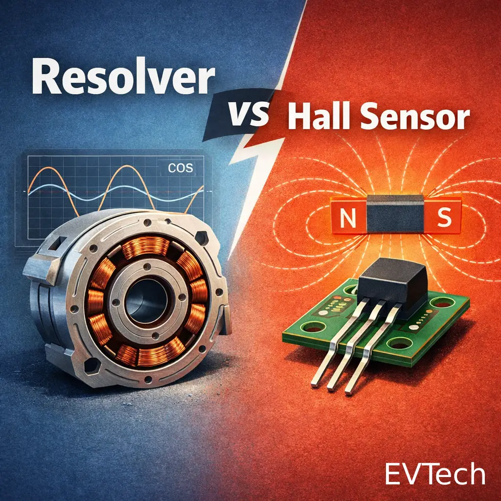
In the New Energy Vehicle (NEV) industry, the resolver is a critical sensor used to measure rotor position and speed within the motor system. The rise of Permanent Magnet Synchronous Motors (PMSMs) has driven the widespread adoption of resolver technology. As an electromagnetic sensor, the resolver—plays a vital role in drive motor systems. It captures the rotor’s angular displacement (position); the derivative of this displacement over time provides the motor’s rotational speed. In motor drive applications, this real-time feedback of position and speed is fundamental to the system’s overall performance.
The working principle of a resolver is similar to a standard transformer. However, while a standard transformer has fixed primary and secondary windings (resulting in a constant voltage ratio), a resolver’s windings move relative to each other based on the rotor’s angular displacement. Consequently, the output voltage varies as a function of the rotor’s position.
Resolvers are the go-to choice for position and speed sensing in EVs, found in traction motors, generators, Electronic Power Steering (EPS) motors, and gas valve angle measurements. Among the various types, Variable Reluctance (VR) Resolvers are most widely used in electric vehicles due to their ease of manufacturing, high reliability, high tolerance for displacement, and low cost.
1.2 ▍ Advantages of Resolvers
Compared to optical encoders, resolvers are better suited for automotive motors because they offer superior feedback quality and durability. While optical encoders are common in industrial automation, resolvers dominate the automotive sector due to their exceptional environmental resilience (vibration/heat resistance) and high-speed performance.
2.1 ▍ Structural Characteristics and Operating Mechanism
Simply put, a resolver is a transformer that rotates. Unlike a standard transformer, its primary winding remains stationary while the secondary winding rotates with the rotor (or vice-versa, depending on the design). In automotive traction motors, the VR resolver is the industry standard. It tracks the rotor’s angular position and outputs feedback via sine and cosine voltage signals.
3.1 ▍ Hardware Decoding Process
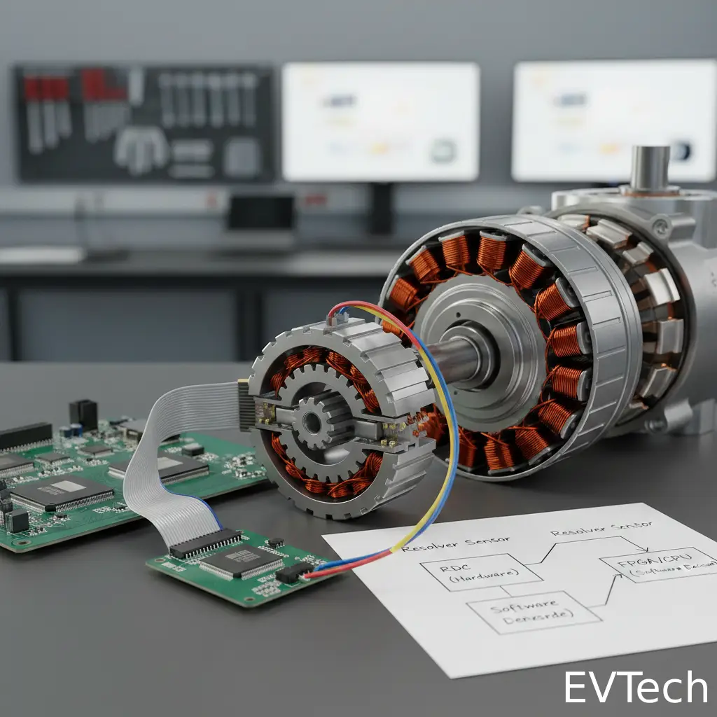
At the hardware level, signal decoding is typically handled by a Resolver-to-Digital Converter (RDC) chip. In this setup, an oscillator generates an excitation voltage. Through a series of sine/cosine multipliers and comparators, the system produces a signal.
Hardware decoding relies on the RDC chip to handle the oscillator, multiplier, and comparator functions, achieving signal demodulation and closed-loop control.
3.2 ▍ Software Decoding Method
Currently, many EV electronic drive systems are moving toward software-based decoding to eliminate the RDC chip and reduce BOM costs. In this architecture, the resolver’s differential output signals (sin+/-、cos+/-) are first processed by a comparator and converted into single-ended sin/cos signals. These signals undergo low-pass filtering and A/D conversion before being sent to an FPGA and CPU.
In software decoding, the FPGA generates the excitation voltage signal and processes the sine/cosine data to calculate the rotor’s angle and speed. Simultaneously, the CPU processes the same signals to perform its own calculations. The CPU then compares, verifies, and corrects its results against the FPGA’s data to ensure maximum decoding accuracy and system safety.