Defining High-Voltage Interlock (HVIL)
In Electric Vehicles (EVs), the High-Voltage Interlock Loop (HVIL) uses low-voltage signals to monitor the integrity of high-voltage (HV) circuits. It is a comprehensive safety mechanism that covers HV components, wiring, connectors, and protective covers. By identifying any abnormal disconnection in real-time, the system can shut down high-voltage power within milliseconds, ensuring the safety of both the vehicle and its occupants.
The Importance of HVIL
HVIL plays a critical role in EV safety. It ensures the integrity of the entire HV circuit, maintaining stable power flow within a closed loop. During vehicle operation, it prevents hazards caused by accidental disconnections or “hot-swapping” (unplugging under load). Furthermore, it effectively prevents arcing—which can occur if an HV connector is pulled while live—providing an extra layer of protection for the hardware and passengers.
HVIL Structure and Design
Because the HVIL operates at a low voltage, its wiring must be physically isolated from high-voltage lines. The operation sequence of HV connectors is vital to prevent current surges:
- When Disconnecting: The HVIL circuit must break before the high-voltage terminals disconnect.
- When Connecting: The high-voltage terminals must engage before the HVIL circuit closes.
HV connectors feature interlock pins and sockets. The loop is closed only when these components are fully mated and opens immediately upon separation.
Classification of HVIL Systems
HVIL monitors are generally categorized by what they protect and their physical design:
- By Application: One type monitors whether HV harness connectors are properly mated, while another detects if the protective covers of HV components (such as the inverter or PDU) have been opened.
- By Design: Common hardware structures include pin-style and spring-tab (shunt) configurations.
Regardless of the design, the objective remains the same: to trigger an immediate alert and safety protocol if a connection is compromised or a cover is removed.
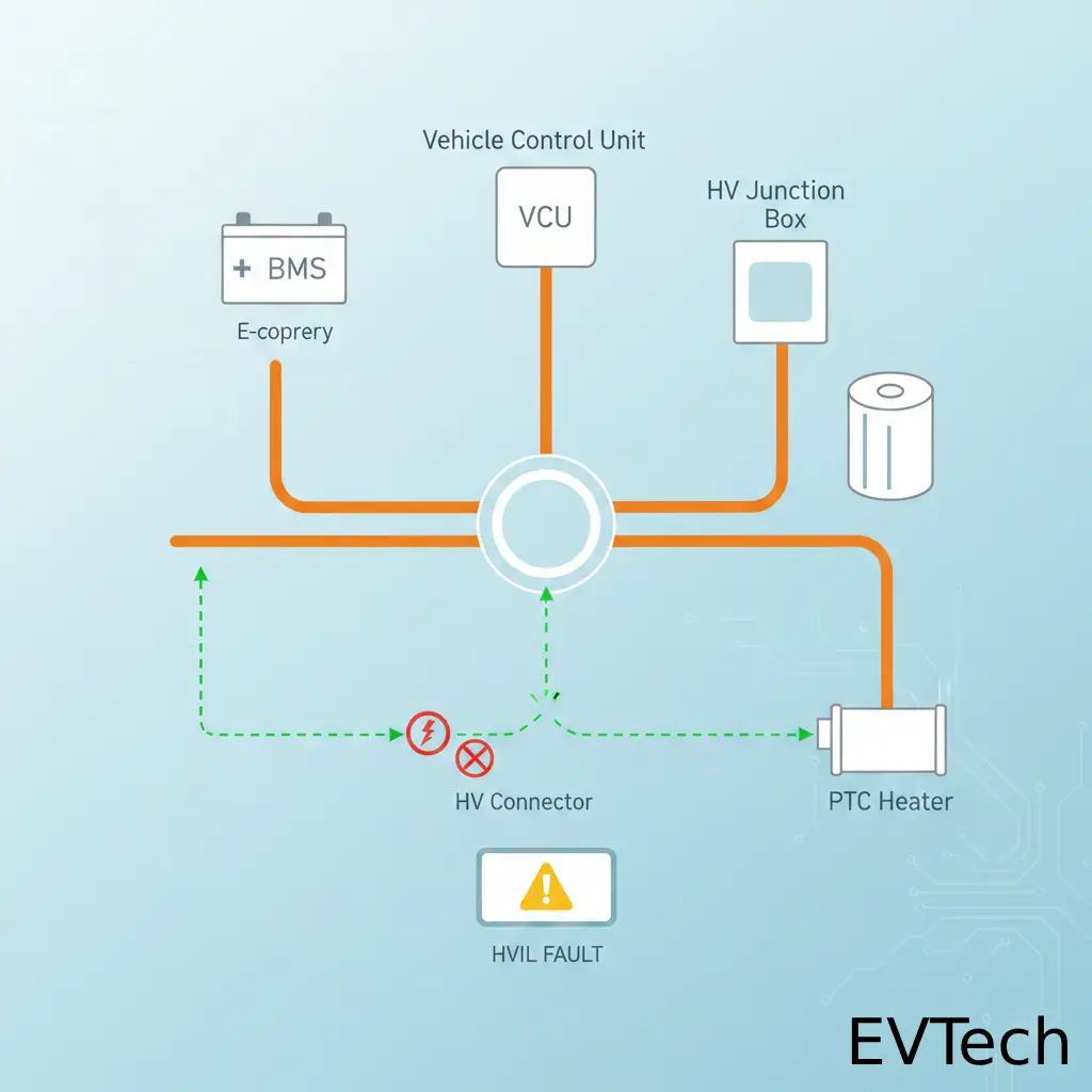
Operating Principles
The monitoring signal is typically generated by the Battery Management System (BMS) or Vehicle Control Unit (VCU). This signal travels through the HV connectors and control boxes to form a complete loop.
Modern systems primarily use Pulse Width Modulation (PWM) for precise monitoring. In this setup, the control unit sends a PWM signal that loops through components like the PTC heater, HV distribution box, and e-compressor before returning to the controller. By analyzing signal parameters—such as the duty cycle—the controller verifies circuit integrity.
If the PWM signal fails to return, it indicates a potential hazard, such as an unseated connector, component damage, or a compromised housing. The advantage of the PWM approach is its ability to distinguish between a simple wiring fault (short/open circuit) and a true high-voltage exposure risk.
HVIL Control Strategies
The system responds to detected faults through a tiered safety protocol:
- Fault Alarms: If a hazard is detected, the unit immediately triggers visual and audible alerts to the driver, regardless of the vehicle’s state.
- HV Shutdown (Stationary): If the vehicle is stationary and a fault is confirmed, the system instructs the VCU to open the high-voltage contactors, cutting power from the battery pack to eliminate risk.
- Power Derating (In Motion): If a fault occurs while the vehicle is at high speeds, the system will not immediately cut high-voltage power to avoid a sudden loss of propulsion. Instead, it warns the driver and enters a “limp home” mode, reducing motor power to gradually slow the vehicle. This allows the driver to pull over safely while minimizing the load on the HV system.


Hi there, all the time i used to check website posts here in the early hours in the morning, since i love to learn more
and more.